9/02/24
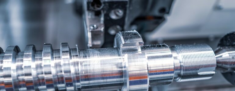
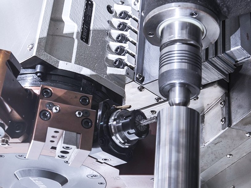
The mechanical industry is constantly evolving, and so are the components that it produces. Nowadays, components come in various shapes and structures, which require high precision and accuracy.
A blank is a piece of material that is ready to be machined into a final product. Aligning the blank correctly on the machine tool is important for ensuring the accuracy and efficiency of the machining process. However, manual alignment and traditional ways can be time-consuming and prone to errors.
To avoid these errors and conduct the machining precisely, engineers need to make sure that the part is in the right place relative to the machine tool and cutting tool.
In this blog, we will show you how 3DeVOK’s portable 3D laser scanners can help you with it by identifying the position and orientation of the blank on the machine tool and correcting the tool path before machining.
We will introduce two cases of aligning, respectively irregularly-shaped blank and forged axle blank, and demonstrate the benefits of our 3D scanning technology.
Alignment for machining is the process of adjusting the position of the blank relative to the machine tool and cutting tool to ensure the quality and accuracy of the machining.
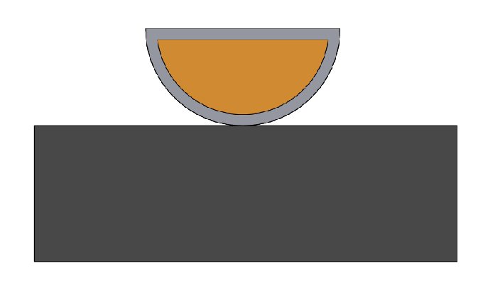
For example, suppose we have a machine tool (black section), a blank (gray section), and a CAD machining model (orange section). Ideally, we want to align them vertically, like this :
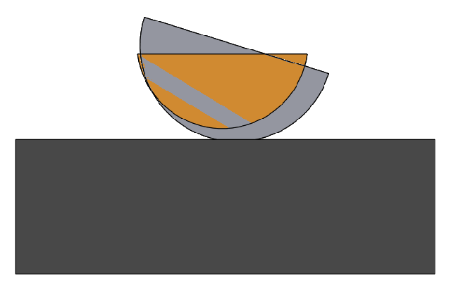
However, in reality, many factors can affect the alignment, such as machining errors and surface roughness. If we do not adjust the position of the blank with the reference of the CAD model, we may end up with parts that don’t have sufficient machining allowances in some areas.
This can ruin the whole workpiece, as shown here:
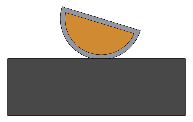
To avoid this problem, we need to measure and correct the position of the blank with the reference of the CAD model. Therefore, we can adjust the machining path accordingly.
This can ensure that the machining allowances are uniform and sufficient, like this:
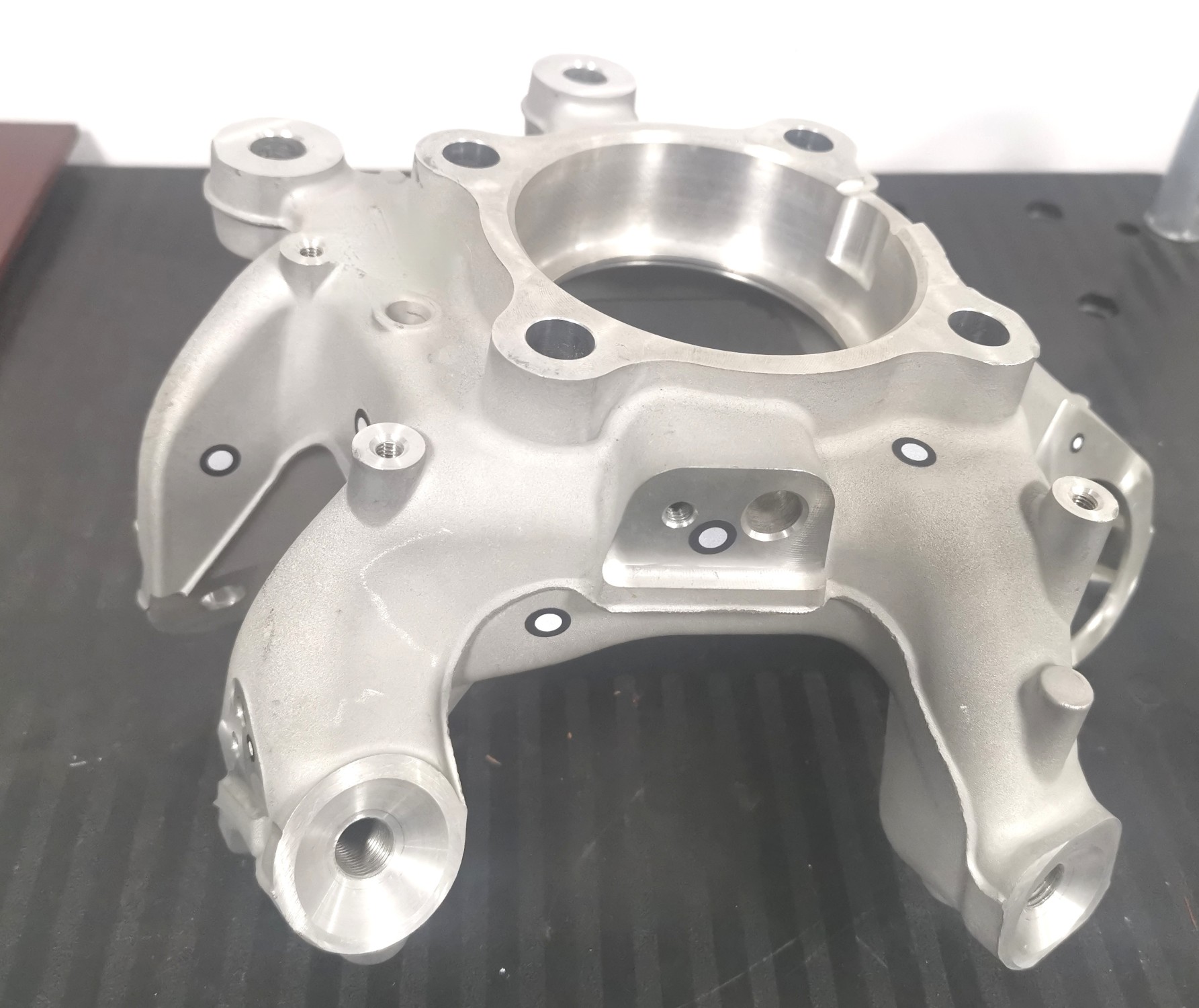
The case involves an irregularly-shaped blank made of cast aluminum alloy. As it is hard to position reliable references, the position of the blank to the machining tool changes every time it is clamped, which affects the subsequent machining.
To solve this problem, we need to scan the geometry of the blank quickly and accurately, and also measure the coordinates of the blank and the machine tool to identify the position relationships.
Then, we can adjust the machining coordinates accordingly, to make sure that there is enough machining allowance on the whole surface of the product. Finally, we can locate the machining reference plane precisely, to guide the following machining steps.
The traditional method to align is manual marking. It requires multiple adjustments and depends on the worker’s experience, which is time-consuming, tedious, and inefficient.
It is hard to position irregular workpieces accurately, which requires many trials and tests. Therefore, it is hard to guarantee the quality of machining and easily leads to defective products.
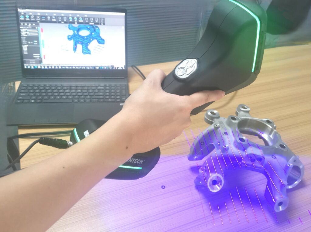
To measure the casting, we followed these steps:
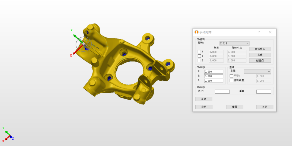
The engineer 3D scanned the full-field 3D data of the casting and aligned the scanned data coordinates with the CAD model.
After the initial alignment, the engineer analyzed the machining allowance and adjusted the coordinates to make sure that the allowance was evenly distributed.
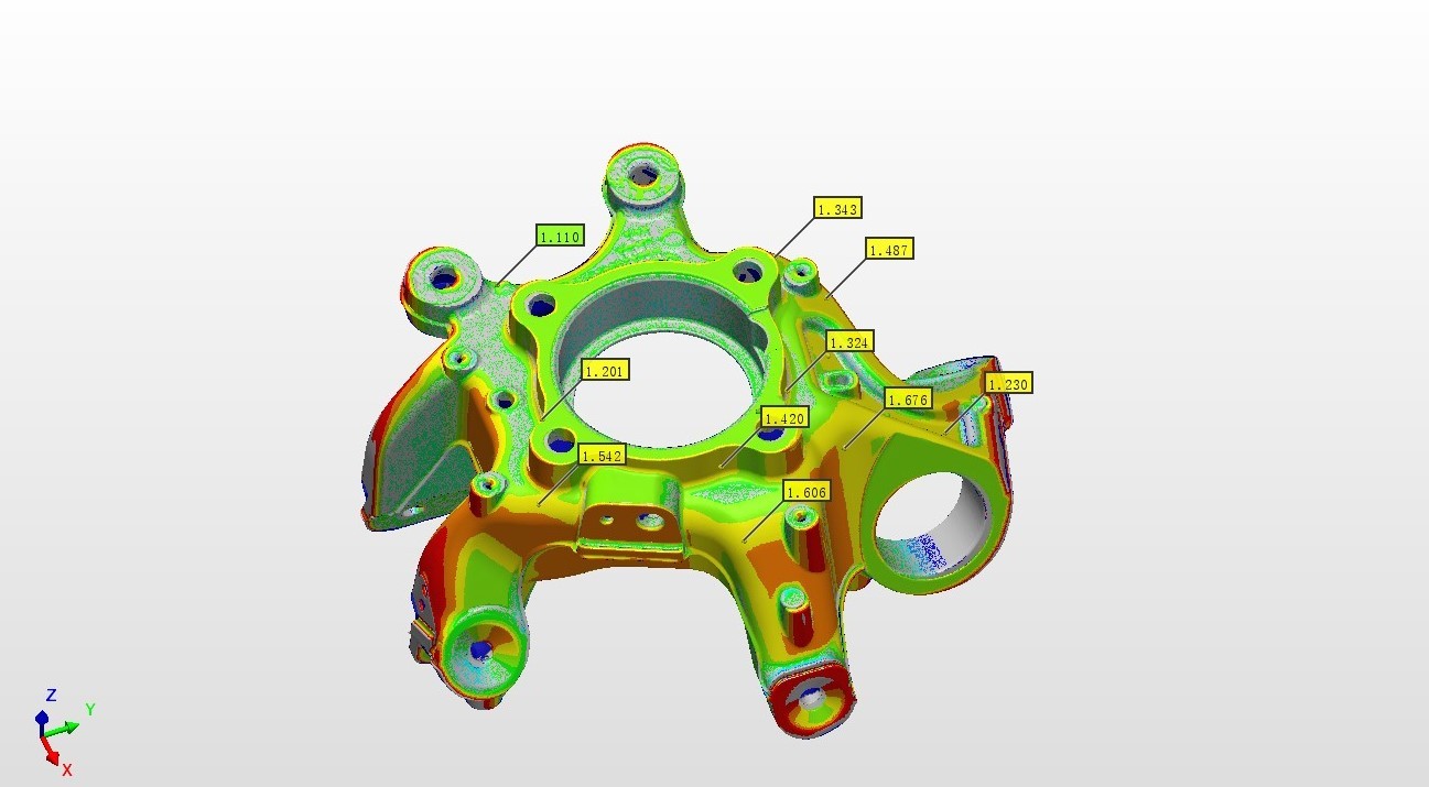
Compared the scanned data with the CAD model and generated a color deviation comparison report.
Transferred the adjusted coordinate system to the machine tool for machining.
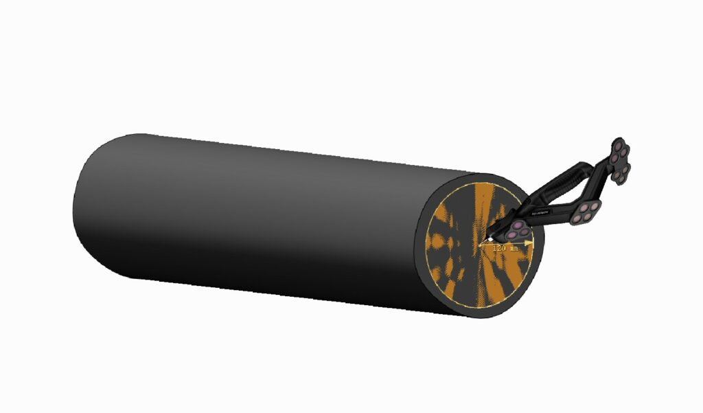
The case involves a large forged axle blank that needs to be machined. To make a precise shaft, the cutting tool touches the shaft blank while it rotates and cuts off some material. The customer needs to align for machining and find the rotating axis.

Measurement Steps
To measure the forged shaft blank, the engineer followed these steps:
Used optical tracking system TrackScan to scan the whole forged shaft blank. Then, aligned the measured coordinate system of the blank with the machining CAD coordinate system. Fine-tuned the coordinates of the blank to make sure that the machining allowance was evenly distributed.
The engineer moved the T-Probe around the part until its coordinates matched the center coordinates shown in the software. In this way, the engineer identified the center of two ends of the blank and found the rotating axis.
The points identified by T-Probe were also used as reference points for clamping.
With a 3D scanner, you can quickly and easily get the full-size 3D data of various parts, without touching them. Even the edges and corners that are hard to reach can be captured completely.
You can then measure the blank allowance comprehensively and make sure it is enough for machining, avoiding waste or defects.
With professional software, you can fine-tune the allowance distribution and quickly and accurately locate the processing reference.
This will help you to machine the blank parts in the next step, without depending on manual experience. This way, you can lower the processing risk and boost the processing efficiency.
The scanner is easy to operate by hand and can be taken to the workshop site. It can handle complex site conditions (such as vibration, temperature, humidity, light, etc.) and perform stably. It can capture the 3D data of various materials and objects effortlessly, saving you time and money.
You can compare the 3D data with the CAD model and get an automatic real-time deviation report. This will provide you with detailed and intuitive data support for determining the machining allowance and aligning the position in the following steps.
 FR
FR