3/03/22
The most common production methods for CFRP moulds is subtractive methods, such as CNC milling. However, with the progress of additive manufacturing, or 3D printing, it is now possible to construct moulds with a more advanced geometry.
In this report a study of the feasibility of using 3D-printed moulds and cores for CFRP molding has been done. The report goes through the process leading up to the molding, the molding itself and the post processing required to achieve the best possible results.
The methods used for preparing the moulds for the moulding process will be described using the PolyMide™ PA6-GF test mould. The whole process includes the first sanding, applying Epoxyprimer, second sanding, adding release agent, moulding and demoulding.
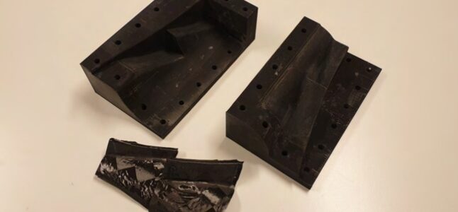
The moulds were first sanded with sanding paper of roughness 80 to 400. In order to remove the largest irregularities on the moulding surfaces a roughness of 80 was needed. After that the moulds were sanded using finer paper up to 400, to get a smooth surface. Figure 1 shows the sanding process, while figure 2 shows the PA6-GF mould after the first sanding had been completed.
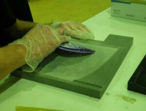
Figure 1: Sanding of PA6-GF test mould
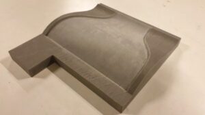
Figure 2: PA6-GF test mould after first round of sanding
After the first round of sanding the Hagmans Spraymax 2K Epoxyprimer Filler was used in order to get rid of unevenness on the surfaces and to add a protective layer for the seal and release agents to be used later. Two layers were applied separated by 10-15 minutes. Figure 3 shows the spraying process by two of the Revolve NTNU team members.
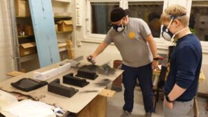
Figure 3: Spraying process using the Hagmans Spraymax 2K Epoxyprimer Filler
Having applied the Epoxyprimer, the moulds were left for around 24 hours to cure and dry. Figure 4 shows the result after all parts had been treated.
When the moulds had dried they were sanded using wet sanding paper with roughness of 800. This is to get the smooth surface finish needed for the moulding process. After that the molds were left overnight to dry once more, before the moulding could commence. Before the fiber was laid, seal and release agents had to be applied, to prevent the fiber from sticking to the moulds. The seal agent used is the Chemtrend Chemlease 712EZ and the release agent is the Chemtrend Chemlease 2185. Three layers of seal and five layers of release was applied for each surface. Figure 5 shows the PA6-GF mould after the seal and release agents had been applied, right before the fiber was laid.
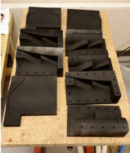
Figure 4: All test moulds after the Epoxyprimer had been applied
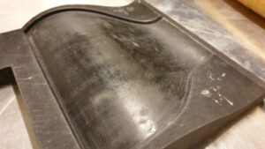
Figure 5: PA6-GF test mould after seal and release agents had been applied
After the last layer of release agent is applied the mold is left for a couple of hours while the foam core (Rohacell IG-F 31) is being dried in the oven to remove any moisture from it. The carbon fiber (Textreme 64gsm with MTC275 50% prepreg) is first being laid into the mold. Then the foam core is added, before a new layer of carbon fiber to create a sandwich structure. Figure 6a shows the first fiber ply being laid in the PA6-GF mould.
After the last ply of fiber is laid, a sheet of release film is laid over the moulded part to prevent the breather from sticking to the fiber. Then the mold is put into a vacuum bag which is being sealed using bagging tape. Then the bag is vacuumed, and the mould put into the oven for around 6 hours at 110◦C. In figure 6b the bagged mould is shown during the vacuuming process.
The mould was cooled for a couple of hours after being cured in the oven. The demoulding process was then performed. Figures 6c and 6d show the part during and right after the demoulding, respectively.
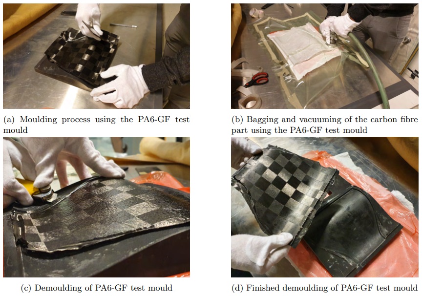
Figure 6: Production of PA6-GF test mould
Figure 7 shows the finished demoulded part next to the used PA6-GF test mould.
The same process as explained above was used for all the test parts and the final parts that were going to be used on the 2021 Revolve NTNU Electric vehicle. While only the steps using the PA6-GF test mould are shown, the process gave sufficient results for the first part and was thus used for the remaining test moulds and the final parts as well. The results for all parts are shown and discussed in section 3.
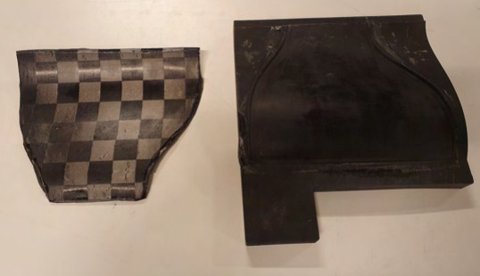
Figure 7: Finished part next to PA6-GF test mould
Due to uncertainty on how much space was needed between the mould and the core for the carbon fiber plies to have enough space, three different types of core were made with different levels of offset from the outer surface of the steering wheel. One with 0.5mm offset, one with 1.0mm offset and one with 1.5mm offset.
The cores were printed in two parts for better print quality. Then the corresponding cores where glued together with 3M Scotch-Weld DP 490 (Figure 8). Sanding of the cores was deemed unnecessary, in the hope that the roughness would help with the bonding between the fibre and plastic.
It was a concern that the lines from the print would have been visible through the thin fibre that was used, however this turned out to not be an issue.
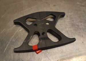
Figure 8: Steering wheel core with 0.5mm offset glued together
The finished part together with the open mould for the test parts are shown in figures 9 and 10, for the CoPA and PA6-GF moulds respectively.
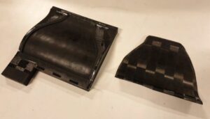
Figure 9: Finished part next to CoPA test mould
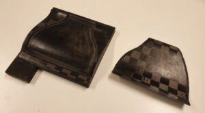
Figure 10: Finished part next to PA6-GF test mould
The PA6-GF mould printed in the orientation seen in figure 7 has a better surface than the one in figure 10. The drawback of this orientation though is that the vertical edges around the moulding surface are not as nice. However, no major problems were encountered for this case during moulding and demoulding, meaning that the orientation in figure 7 gave the best overall result.
During demoulding it was evident that the moulds made of PA6-GF had both deformed significantly. While it did not look like it had affected the shape of the actual part, the PA6-GF is not suitable for this kind of application using high temperatures.
The moulded part and closed mould using CoPA is shown in figure 11. The finished part turned out mostly good, but some treatment had to be done. It seemed that the mould had not deformed noticeably, meaning this material should be suitable for similar applications.
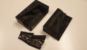
Figure 11: Finished part next to CoPA closed test mould
The last two closed mould gave some mixed results. While the PA6-GF and CF mould did not seem to deform at the moulding surfaces, some problems with applying the release agent meant that the final result did not turn out well. This had most likely nothing to do with the mould material though. As for the open mould the PA6-GF material seemed to deform slightly, but as mentioned before did not affect the shape of the part. This means that the PA6-CF material should work for closed mould applications.
The PC closed mould completely deformed during curing in the oven at 110◦C, and it was impossible to demould to see the result of the part. This means that PC is not suitable for carbon fiber moulding where the temperatures used are close to 110 degrees C.
Revolve NTNU mostly uses MDF in the moulding process of the carbon fiber parts. The 3D printed moulds was much quicker to prepare for moulding than MDF, as the MDF need to be sealed to prevent moisture getting into the parts during the curing process. The challenge for 3D printed moulds is the size limitation. Milled MDF parts may be thousands of millimeters in length and width, while 3D printed parts are limited to a few hundred. This means that larger parts may not be moulded using 3D printed moulds.
The ST Guide Wall parts were similar to the open test moulds described earlier. The difference was that an intensifier was added on one end to shape the part in order to fit when mounted on the vehicle. The mould was made of CoPA, which was also used for one of the test moulds. The result is shown in figure 12. The part turned out good, and has been fitted to the vehicle, as seen in figure 13.
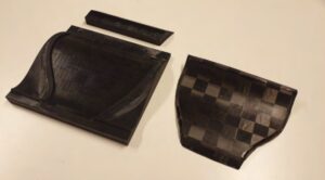
Figure 12: Finished part next to CoPA mould for part on car
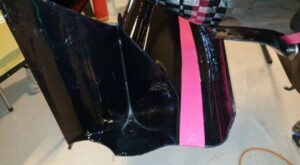
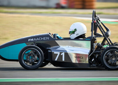
Figure 13: Finished part mounted on the sidetray of the 2021 Electric vehicle
For the steering wheel, both the core and mould where 3D-printed. The material used for all of the prints in this section was PolyMide™ PA6-CF and PolyMide™ PA12-CF, and two layers of fibre on the core (Figure 15c). The finished steering wheel was placed in the car to see that it did actually fit as it should (Figure 14). To achieve this nice surface finish, it was used 500+ sand paper and clear coat.
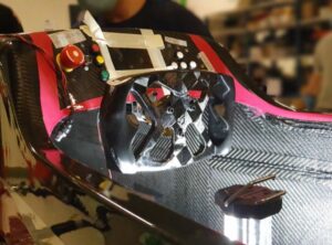
Figure 14: Finished steering wheel mounted with temporary grips in the 2021 Electric vehicle
After assessing the different cores together with the mould, it was decided that the core with 1.5mm offset did not fit at all, as 1.5mm was too high. There would have been zero pressure on large parts of the CFRP, resulting in dry fibre. Therefore it was decided to try the cores with 1.5mm offset without a mould, to see what kind of results that would give. The core with 0.5mm offset did barley fit, however it was decided that with the Textreme 64 gsm fibre (thickness of 0.064mm) it looked possible.
The core with 1.0mm offset did not get tested due to time constrains. However, with a thicker fibre than Textreme 64 gsm, it could be possible to use this one as well. This would result in a heavier but stronger part.
The treatment of the steering wheel mould was a bit more difficult than the others. This is because of the much more complex geometry, with its tight spots where it is hard to sand properly. This resulted in spots where it was not possible to get a smooth surface. If the CFRP was laid with this rough surface there was fear that it would never come out again. The solution was to use Teflon tape on the mould, where the roughness was worst (Figure 15d).
After two layers of Textreme 64 gsm was applied on the 0.5mm offseted core (Figure 15a), it was placed in the mould. This was quite a task as it just barley fitted. A shock absorbing hammered was used to force it all the way down in the mould. However, this meant that there was no question that the fiber had enough pressure on the sides.
After demoulding it could be seen that there was some spots with dry fibre. This is probably because of missing pressure. However, the majority looked very good. After some hours of sanding the result turned out sufficient.
The steering wheel that was moulded without using a mould, did not turn out as good as hoped (Figure 15b). The first problem was the fact that it was partially melted on just one side. This also resulted in that the geometry changed, thus this part cannot be used. The reason might be because the two different core parts was made up of two different materials or thicknesses. Therefore only one of them was strong enough to survive the pressure and temperature. The second problem was the extremely rough surface finish. This is not necessarily a big problem, however it would need a lot of post processing to achieve the same surface finish as with a mould.
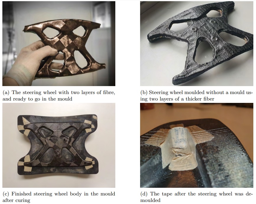
Figure 15: Steering wheel production process
For the open moulds the orientation used for the PolyMide™ PA6-GF mould in figure 2 gave the best surface finish, while the CoPA material is the most suitable due to it not showing any signs of deformation.
The closed mould made of CoPA have good results. While the PA6-GF and PC moulds deformed, the PA6-CF mould seemed to work rather well, meaning that it should be suitable for these kind of applications.
3D-printed cores have proven to be a viable option, with the right offset. Although you should still use a mould for the best results. It is however important to have sufficient structural integrity so that the core does not collapse under the pressure and temperature used during the curing process.
Article from our partner Polymaker
Authors
 FR
FR